Introduction
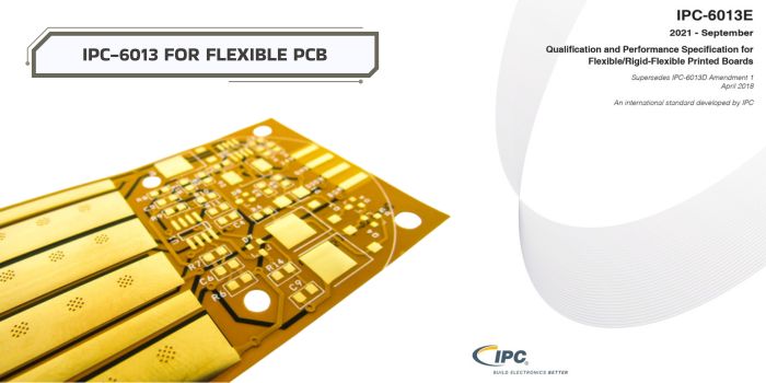
IPC-6013 defines qualification and performance requirements for flexible and rigid-flex printed boards. For manufacturers, it turns flex PCB quality into measurable expectations for materials, plating, coverlay, holes, inspection, testing, and reliability. Understanding it early helps reduce defects, improve yield, and build circuits suited for real bending, assembly, and field use.
What is IPC-6013 in Real Manufacturing?
IPC-6013 is a quality standard used for flexible PCB and rigid-flex PCB manufacturing. Its full purpose is to define how these boards should be built, tested, and inspected so they can perform well in real products.
IPC-6013 helps manufacturers know what is acceptable and what is not acceptable during production.
It covers many important areas, such as:
- material quality
- copper conductor condition
- hole plating reliability
- coverlay alignment
- electrical performance
- mechanical strength
- cleanliness
- final inspection standards
In real manufacturing, IPC-6013 is not only used at the final inspection stage. Good PCB factories use it during the full production process.
For example:
- During engineering review, it helps choose the right materials.
- During drilling and plating, it helps control hole quality.
- During lamination, it helps check bonding strength.
- During final testing, it helps verify continuity and insulation.
This is important because flexible PCBs have risks that rigid boards may not have. Flex circuits bend, twist, and move. Because of that, they can face problems like:
- copper cracking
- adhesive failure
- layer separation
- dimensional movement under heat
- stress near bend areas
IPC-6013 helps reduce these risks by setting clear manufacturing targets.
Another key benefit is communication. When a buyer asks for an IPC-6013 Class 2 or Class 3 board, both the customer and manufacturer understand the expected quality level. This reduces confusion and helps avoid costly mistakes.
Why IPC-6013 Matters in Flexible PCB Production
Flexible PCB materials are thinner and softer than rigid boards. They react more to heat, pressure, and movement. Because of this, normal PCB rules are often not enough.
IPC-6013 matters because it focuses on problems common in flex production, including:
- bend area damage
- coverlay lifting
- plated hole weakness
- misalignment after lamination
- conductor fatigue after repeated motion
Types of Flexible PCBs Covered Under IPC-6013
IPC-6013 also classifies boards by printed board type. These five types explain how the board is built and how complex it is to manufacture.
Single-Sided Flexible PCB
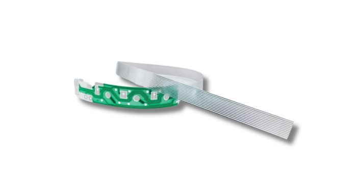
Type 1: Flexible printed boards are single sided and are made with one conductive layer and may have stiffeners where necessary.
These are used for simple circuits, cable replacements, and products that need easy bending.
Double-Sided Flexible PCB
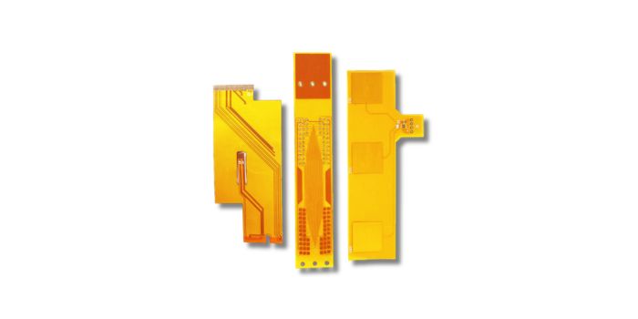
Type 2: Flexible printed made with two conductive layers, one over the other, and connected by plated through holes with or without supporting stiffeners.
They allow more routing space and are common in industrial and consumer electronics.
Multilayer Flexible PCB
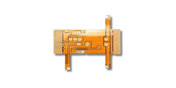
Type 3: Flex boards with three or more conductive layers and plated through holes, and may contain stiffeners as necessary.
These are used in compact and advanced electronics that need higher circuit density.

Rigid-Flex PCB Assemblies
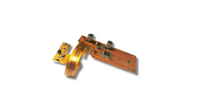
Type 4: Boards that are made of rigid material mixed with flexible material with three or more conductive layers and plated through holes.
They combine rigid sections for components and flexible sections for bending.
Multilayer Without PTH
Type 5: Flexible or rigid-flex boards constructed using two or more conductive layers but without plated through holes.
These designs are used in special applications where plated holes are not needed.
Each board type needs different materials, process control, inspection, and cost planning. Knowing the correct IPC-6013 type helps manufacturers build the board correctly from the start.
IPC-6013 Classes for Flexible PCB Manufacturing
IPC-6013 groups flexible PCBs into three quality levels: Class 1, Class 2, and Class 3. These class meanings are based on the IPC-6011 standard.
Class 1 – Functional, Low-Risk Electronics
Class 1 applies to products where basic function is the main requirement and limited service life is acceptable. Examples may include simple consumer electronics, toys, disposable devices, or non-critical accessories.
For flex PCB manufacturing, Class 1 usually allows the least stringent acceptance criteria. However, the board still needs to meet the agreed drawing, electrical requirements, and baseline workmanship expectations.
Class 2 – Industrial and Commercial Applications
Class 2 is the default performance class if procurement documentation does not specify otherwise under IPC-6013E default selections.
This class is common for commercial, industrial, automotive-adjacent, communication, instrumentation, and durable electronic products where continued performance and longer service life matter.
Class 3 – High Reliability Applications
Class 3 is used when failure could create serious risk, high replacement cost, or mission-critical downtime. Typical applications include aerospace, defense, medical devices, high-end industrial controls, and safety-related electronics.
Class 3 flex PCB manufacturing demands tighter process control, stronger documentation, higher inspection discipline, and more conservative design choices around bend areas, plating, hole quality, and material stability. Meeting these stringent criteria is a core part of achieving total compliance in flexible PCB manufacturing for mission-critical industries.
Core IPC-6013 Manufacturing Requirements
Material Selection Standards
IPC-6013 allows the procurement documentation to define required material selections; if not specified, certain defaults apply. In IPC-6013E, the default material selection is fabricator-defined unless the drawing or procurement package states otherwise.
In real manufacturing, material selection should consider:
- Polyimide thickness
- Adhesive vs adhesiveless copper-clad laminate
- Rolled annealed vs electrodeposited copper
- Coverlay type and adhesive system
- Stiffener material
- Flame rating or UL requirements
- Thermal exposure during assembly
- Dynamic vs static bending use
For dynamic high-flex scenarios, adhesiveless laminates and rolled annealed copper are preferred, delivering superior flex fatigue performance compared to adhesive-rich substrates.
Copper Foil and Conductor Integrity
Copper integrity is one of the most important flex PCB reliability factors. IPC-6013E’s table of contents includes requirements for finished external conductor thickness after plating, internal layers, conductor characteristics, and related quality criteria.
Manufacturing risks include:
- Over-etched conductors
- Thin copper at trace edges
- Cracks in bend zones
- Copper fatigue from repeated movement
- Poor plating distribution
- Stress concentration at sharp corners
Best practice is to use smooth routing, avoid 90-degree corners in bend areas, balance copper distribution, and keep vias and plated holes away from high-strain flex zones whenever possible.
Coverlay Bonding and Registration
Coverlay protects conductors in the flexible area. Poor coverlay registration can expose copper, reduce insulation spacing, interfere with pads, or create weak points near bend regions.
IPC-6013 manufacturing control should focus on:
- Coverlay opening accuracy
- Adhesive squeeze-out control
- Bond strength
- Wrinkle prevention
- Void prevention
- Proper clearance around pads and traces
Coverlay defects are often process-related, so a compliant manufacturer should control lamination pressure, temperature, tooling registration, and material storage.

Hole PTH Wall and Interconnection Reliability
For Type 2, Type 3, and Type 4 boards, plated-through hole reliability is critical. IPC-6013 includes performance expectations for PTHs, interconnections, plated internal layers, dielectric removal, and microvia-related structures.
Key issues include:
- Thin hole-wall copper
- Barrel cracks
- Wicking
- Poor desmear
- Voids in plating
- Inner-layer separation
- Pad lift after thermal stress
Because flex materials move more than rigid laminates during processing, hole quality depends heavily on drilling control, plasma or chemical preparation, plating uniformity, and thermal stress testing.
Dimensional Stability
Flexible materials expand, shrink, and distort more easily than rigid FR-4. Dimensional stability affects coverlay alignment, hole-to-pad registration, stiffener placement, impedance control, and assembly fit.
Manufacturers control this through material pre-bake, panel compensation, lamination recipes, controlled humidity, tooling systems, and in-process measurement.
Mechanical Requirements for Flex PCB Reliability
Bend Performance
IPC-6013 defines installation usage categories. Use A applies to flexing during installation, while Use B applies to ongoing flexing for the number of cycles listed in the procurement documentation.
Bend performance depends on:
- Bend radius
- Copper type
- Copper thickness
- Number of layers
- Total flex thickness
- Adhesive thickness
- Trace direction
- Dynamic cycle count
- Placement of vias, pads, and stiffeners
IPC-2223 is the companion design standard for flexible and rigid-flex boards, and its content includes bend radius, conductors in bend areas, bend/crease center lines, neutral axis construction, bend ratio, and bookbinder construction.
Wrinkles, Creases
Wrinkles and creases can indicate material stress, lamination problems, improper handling, or excessive bending. In flex PCB production, these defects are serious because they may lead to copper cracking, dielectric thinning, delamination, or insulation failure.
A manufacturer should inspect for:
- Creases crossing conductors
- Wrinkles near coverlay edges
- Buckling in unbonded layers
- Stress marks near stiffeners
- Localized delamination
Transition Zones
Rigid-to-flex transition zones are among the highest-risk regions in rigid-flex manufacturing. IPC-6013E includes updated requirements related to rigid-to-flex transition zones.
Good transition-zone design avoids:
- Vias too close to the rigid-flex boundary
- Abrupt copper changes
- Stiffener edges ending at bend points
- Coverlay termination at high-stress locations
- Sharp corners in the flex outline
IPC-6013 Inspection and Quality Control
Visual Criteria
IPC-6013 works with other IPC documents such as IPC-A-600 for acceptability of printed boards. IPC-A-600 is used for visual inspection criteria, including defects such as cracks and delamination.
Visual inspection should cover:
- Surface defects
- Coverlay alignment
- Conductor nicks
- Scratches
- Exposed copper
- Delamination
- Blisters
- Foreign material
- Plating defects
- Stiffener alignment
Electrical Testing
Electrical testing verifies opens, shorts, continuity, and isolation. IPC-9257 is commonly referenced for electrical testing procedures, while IPC-TM-650 contains standardized test methods used across PCB materials and processes.
For flex PCBs, electrical testing should be paired with mechanical and thermal validation because a board may pass continuity before bending but fail after flexing or assembly heat exposure.
Structural Defect Detection
Structural reliability is checked through methods such as microsection analysis, thermal stress testing, peel strength testing, insulation resistance testing, and dielectric withstand testing. IPC-6013E includes tables for dielectric withstand test voltages, insulation resistance, qualification testing, acceptance testing, and quality conformance testing.
Process Control and Trend Monitoring
IPC-6013 compliance is strongest when it is supported by process control, not just final inspection. A capable manufacturer should monitor:
- Etch compensation
- Plating thickness
- Lamination parameters
- Registration accuracy
- Drill quality
- Coverlay alignment
- Yield loss by defect type
- Microsection trends
- Electrical test failure patterns
Why IPC-6013 Should Influence PCB Design Early
Bend Radius and Flex Layout
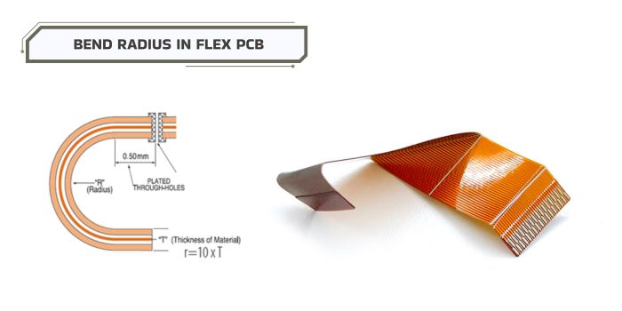
Bend reliability must be designed before fabrication. IPC-2223 covers bend radius, conductors in bend areas, neutral axis design, bend ratio, and related flex construction topics.
Early design choices should include:
- Keeping traces perpendicular to bend direction when possible
- Avoiding vias in bend regions
- Using curved traces instead of sharp corners
- Balancing copper across layers
- Keeping bend areas thin
- Defining static vs dynamic flex use
- Specifying cycle requirements for dynamic flex
Material Stack-Up Planning
The stack-up determines thickness, flexibility, impedance, thermal behavior, and cost. A stack-up that works electrically may still fail mechanically if it is too thick or poorly balanced.
Designers should involve the fabricator early to select copper weight, dielectric thickness, adhesive system, coverlay, stiffeners, and final finish.
Cost vs Yield
Higher IPC class, tighter tolerances, thinner materials, dynamic bend requirements, controlled impedance, and complex rigid-flex structures all increase cost. However, designing for IPC-6013 early often reduces total cost by preventing scrap, redesign, delayed qualification, and field failures.
Common IPC-6013 Compliance Challenges
Copper Cracking
Copper cracking usually comes from excessive bend stress, poor copper selection, sharp trace geometry, thick copper, or repeated dynamic flexing beyond the design limit.
Prevention:
- Use rolled annealed copper where appropriate
- Increase bend radius
- Reduce copper thickness in bend areas
- Avoid vias and pads in bend zones
- Use gradual trace transitions
Coverlay Misalignment
Coverlay misalignment can expose conductors, reduce spacing, or interfere with solderable pads.
Prevention:
- Use correct coverlay clearances
- Allow realistic registration tolerance
- Design larger openings where possible
- Confirm manufacturer capability before release
Adhesion Failures
Adhesion failures may appear as delamination, blistering, coverlay lift, or copper peel issues. IPC-TM-650 includes peel strength testing methods used to assess copper-to-substrate adhesion.
Prevention:
- Choose compatible materials
- Control lamination parameters
- Avoid moisture contamination
- Verify material shelf life and storage
- Use proper surface preparation
Thermal Movement Issues
Flex materials expand and contract during lamination, soldering, and reflow. IPC-6013E requires procurement documentation to specify thermal stress test method and number of cycles, with default selections applying if not specified.
Prevention:
- Define assembly reflow conditions
- Use suitable materials for lead-free processing
- Control moisture
- Validate with thermal stress testing
- Avoid overly tight registration where materials cannot support it
Plating Defects
Plating defects include voids, thin copper, nodules, cracks, and poor through-hole coverage. These defects are especially critical in flex and rigid-flex because bending and thermal cycling can accelerate failure.
Prevention:
- Require microsection verification
- Monitor plating thickness
- Control drill smear removal
- Use suitable coupons
- Audit plating process capability
How to Choose an IPC-6013 Compliant PCB Manufacturer
Engineering Expertise
Choose a manufacturer that understands flex-specific design issues, not just rigid PCB fabrication. They should review bend radius, stack-up, transition zones, stiffeners, coverlay openings, via locations, and material choices before production.
Testing Capabilities
A qualified manufacturer should support electrical testing, microsection analysis, thermal stress testing, peel strength testing, insulation resistance testing, and bend-related validation when required. IPC-TM-650 is commonly used for standardized test methods such as flexural endurance, peel strength, HiPot, thermal shock, and impedance testing.
Flex PCB Production Experience
Experience matters because flexible materials are harder to control than rigid laminates. Ask about:
- Similar products manufactured
- Dynamic flex experience
- Rigid-flex transition-zone capability
- HDI flex capability
- Minimum line/space
- Minimum coverlay registration tolerance
- Plating and microsection history
Quality Certifications and Traceability
IPC-6013 compliance should be supported by documented quality systems. Look for ISO 9001, UL recognition where required, lot traceability, material certificates, inspection reports, test coupons, first article inspection, and clear control plans.
Conclusion
IPC-6013 is the main performance and qualification standard for flexible and rigid-flex PCB. It affects material selection, construction type, class requirements, plating, coverlay quality, hole reliability, inspection, testing, and procurement documentation. For reliable flex PCB manufacturing, IPC-6013 should guide the project from design review through production release.
MV Flex Circuit has over 20 years of experience manufacturing flexible and rigid-flex circuits. We support up to 8-layer flex circuits and 20-layer rigid-flex circuits, with all products produced in strict compliance with IPC-6013 Class 2/3 standards. We are fully certified to ISO, UL, REACH and RoHS. Send us your Gerber files today for a free DFM check and quotation.