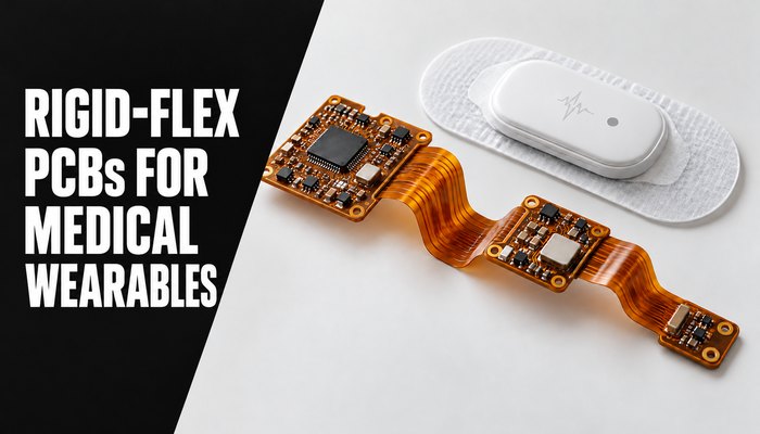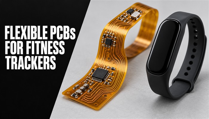
Designing compact flexible PCBs for fitness trackers needs careful planning. You must plan the sensors, batteries, wireless parts, and circuit layout. A flexible PCB helps you fit these parts into small spaces and can reduce the need for separate wires and connectors.
This guide explains when to use flexible PCBs in fitness trackers and what to consider during design, PCB assembly, and testing.
Why Use Flexible PCBs in Fitness Trackers?
A flexible PCB gives you more design freedom compared to a rigid PCB. Flexible circuits can fit into curved spaces and support bending when designed with the proper bend radius. You can also connect sensors and other components without extra wiring.
Flexible circuit boards help reduce circuit thickness and weight. Combining connections in one circuit structure can simplify the electronic design and reduce separate interconnects.
These benefits matter as fitness trackers gain more features. GPS and ECG monitoring, for example, can add to the electronic demands of a device. You need a circuit design that supports these functions without taking up too much space. IPC-2223 design guidance for flexible and rigid-flex printed boards provides a useful starting point alongside your manufacturer’s design rules.
When Should You Choose a Flex PCB?
The choice of a PCB depends on the product’s shape, space, and mechanical requirements. Wrist movement does not necessarily mean that the circuit inside the housing bends. Distinguish a circuit folded during assembly from a flex section that moves repeatedly in use.
Curved Design
Wearable fitness trackers follow the shape of a wrist. A flexible circuit can fit body-contoured housings more easily than a single rigid board.
Bend Cycles
Daily movement can put stress on internal connections. For designs with moving flex sections, consider the expected bend cycles, copper type, stackup, and bend radius to reduce the risk of fatigue failure.
Weight and Size
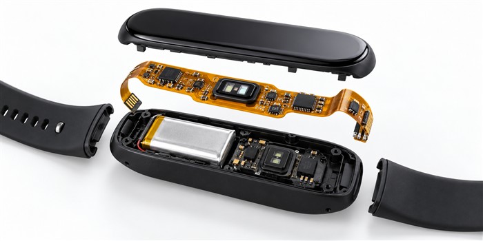
Fitness trackers come in different shapes and thicknesses. A slim tracker has little space for its circuit and components. A flex PCB can fit into thin, narrow areas while supported regions provide stable mounting for parts.
Simple Connections
On a flex PCB, you can combine several connections into one circuit structure. This can reduce separate wiring and connectors, simplify assembly, and remove some potential failure points.
Some trackers need stable mounting areas for multiple components. In these cases, a rigid-flex PCB combines rigid sections with flexible interconnections. Place components on supported rigid areas and use flexible sections where the circuit needs to bend.
Key Design Considerations for Fitness Tracker Flex PCBs
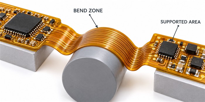
Mark Bend Zones and Supported Areas
Start by marking the areas where the board will bend. These are called bend zones. Also mark areas that need extra support for chips, batteries, and connectors. Keep components out of moving bend zones and plan a gradual transition between supported and flexible regions.
Plan Copper Traces and Coverlay
Copper traces and copper thickness affect the board’s electrical and mechanical performance. Route traces through bend zones with the appropriate radius and avoid abrupt changes that concentrate stress. Keep vias away from areas that bend repeatedly.
A coverlay protects the copper, but its material and adhesive also affect the stackup. Plan coverlay openings, clearances, and alignment with the manufacturer.
Choose Materials and Layers Carefully
Polyimide is a common choice because it offers flexibility and high thermal stability. Copper type matters too. Rolled annealed copper is commonly considered for repeated-flex applications, but the full construction and bend conditions determine fatigue life.
Plan the number of layers around routing needs, thickness, cost, and mechanical behavior. Review the material system with the PCB manufacturer before finalizing the design.
Place Components with Care
Batteries, connectors, and other mechanically loaded parts need firm support. Use rigid sections or suitable stiffeners beneath component areas, and reserve flexible regions for bending. Low-profile components help keep the tracker thin.
Always test the board with a prototype before going into bulk production.
Common Assembly Challenges and How to Address Them
Holding Thin Boards Flat
Thin boards can fold or tear during placement. Vacuum handling can also pull an unsupported board out of position. Custom carriers help support the full circuit and keep it flat during assembly.
Controlling Solder Paste
Too much solder paste can bridge nearby pads and cause faults. Use an appropriate stencil design and a controlled printing process to place the right amount of paste on each pad.
Managing Reflow Heat
Excessive soldering heat can damage flexible materials and adhesive layers. Set a reflow profile that meets the component, solder, and laminate requirements, and control the time spent at high temperature.
Preventing Component Movement
Board movement and uneven heating can affect alignment and contribute to small-component assembly defects. Use suitable stiffeners, stable carriers, balanced pad designs, and a validated placement and reflow process.
Protecting Coverlay During Inspection and Rework
A weak coverlay bond can affect board quality. Inspect adhesion and surface defects against agreed acceptance criteria. During rework, control soldering temperature and heating time to avoid damaging flexible materials.
Check for electrical faults, visible damage, weak solder joints, and other assembly issues. If the board bends during use, test it under the expected operating conditions.
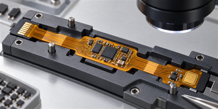
Why Polyimide Is Commonly Used in Wearable Flex Circuits
Flexibility and Fatigue Performance
Polyimide supports thin, flexible constructions, but the substrate alone does not guarantee a fixed bend-cycle life. Copper, total thickness, bend radius, routing, and test conditions all affect durability. Validate the assembled circuit against its intended motion rather than assuming a universal cycle count.
Sweat, Lotions, and Moisture
Fitness trackers face sweat and body lotions during daily use. Chemical resistance and moisture absorption vary with the polyimide grade, adhesive, coverlay, and complete assembly. Some specialized grades offer lower moisture uptake; do not assume all polyimide has the same properties.
Check the relevant supplier data, such as Kapton polyimide film information from Qnity, and validate the enclosure and protective materials for the intended exposure. The flex substrate alone does not make a tracker waterproof.
Thin Construction
Polyimide base films are available in thin gauges, including approximately 25 to 50 micrometers for some grades. The finished PCB is thicker because it also includes copper, coverlay, adhesives, and any stiffeners. Review the complete stackup when planning a compact tracker.
Thermal Stability
Polyimide is commonly selected for soldering processes that require more thermal resistance than many PET- or PEN-based constructions. Actual temperature limits and dimensional behavior depend on the specific film, adhesive system, and processing conditions.
Steps to Build and Test a Reliable Fitness Tracker PCB
- Review the design with the manufacturer. Check bend radius, materials, copper thickness, layer count, supported areas, and panel layout before fabrication.
- Prototype and evaluate. Use design tools to identify weak points, build test boards, and use prototype feedback to improve fit, assembly, and performance.
- Inspect and verify. Perform visual inspection, electrical checks, and functional tests. Use the agreed IPC-A-610 revision and acceptance class where applicable for assembly inspection.
- Test the expected environment and motion. Select appropriate sweat exposure, humidity, temperature, and bend-cycle tests for the finished product. Salt fog alone is not a direct substitute for a defined artificial-perspiration test.
These steps help find faults early and support consistent quality as production increases. For related pitfalls, see our guide to avoiding common flexible PCB errors.
Frequently Asked Questions
What Should You Consider When Designing a Fitness Tracker Flex PCB?
Key factors include bend zones, bend radius, copper thickness, layer count, trace routing, via placement, coverlay protection, and component support. Confirm whether the circuit only folds during assembly or must flex repeatedly in use.
Why Is Polyimide Used in Fitness Trackers?
Polyimide offers flexibility and thermal stability in thin constructions. Select its grade and the complete material system around the required assembly process, moisture exposure, and mechanical testing.
Is a Flex PCB Always Better Than a Rigid PCB?
No. Rigid PCBs work well when a circuit needs a stable shape and fits the available space. Flex PCBs offer more freedom for curved or compact layouts. Rigid-flex constructions can combine stable component mounting with flexible connections.
Conclusion
Flexible PCBs help you build slim and lightweight fitness trackers. They fit curved shapes and connect sensors in small spaces. With appropriate materials, supported component areas, careful assembly, and application-specific testing, you can develop circuits that suit daily wearable use.
Planning a compact wearable circuit? Send your design requirements and Gerber files to MV Flex Circuit to discuss materials, stackup, assembly, and a quotation.